Robot Drink Machine
December 2021
Goal
It’s been a while since I’ve built any projects just for fun with no strings attached so the goals for this project were pretty simple.
- Have fun
- Mix a variety of drinks automatically
- Low complexity
- Low cost / using materials I already had
Inspiration
Austin Scott of Dragos built a robot bartender called “Sir-Mix-a-Bot” which can be seen here. It’s a very cool design. However, I wanted to approach the problem a little differently.
Even though Programmable Logic Controllers (PLCs) are very good at handling lots of I/O and are very useful for industrial processes, I knew that for the size/scale of system I wanted to build that it would be overkill. Therefore, I opted for a more simplistic design. I wasn’t designing this for educational/demonstration purposes so minimum viable product was the priority.
Materials
| Component | Quantity | Product Page | Price |
|---|---|---|---|
| 12.9” x 35mm x 7.5mm Aluminum DIN Rail | 1 | Link | $6.99 |
| DIN Rail Terminal Blocks | 1 | Link | $25.98 |
| SainSmart 8-Channel Relay | 1 | Link | $10.99 |
| Gikfun 12V DC Dosing Pump | 8 | Link | $11.98 |
| 2mm ID x 4mm OD High-Strength Silicone Tubing | 5 | Link | $8.59 |
| 3/4” 90 degree PVC fitting | 1 | Link | $0.48 |
| 18 Guage Solid Core Wire | 1 | N/A | < $10 |
| Alligator Clips | 16 | N/A | < $10 |
| Breadboard Jumper Wires | 9 | Link | $6.98 |
| Emergency Stop Normally Closed Stop Switch | 1 | Link | $14.98 |
| 24V 3A DC Power Supply Adapter | 1 | Link | $14.99 |
| WAGO 221 Lever-Nuts | 1 | Link | $25.00 |
| Raspberry Pi 3B | 1 | Link | $35.00 |
| 7 Inch Portable Raspberry Pi Touch Screen | 1 | Link | $76.49 |
Total Approximate Cost: $258.45 + Wood for a Stand (~$35) = $293.45 USD
Design
For the initial design work, I split the project into four different pieces, the pump design, the logic design, programming, and the physical design.
Pump Design
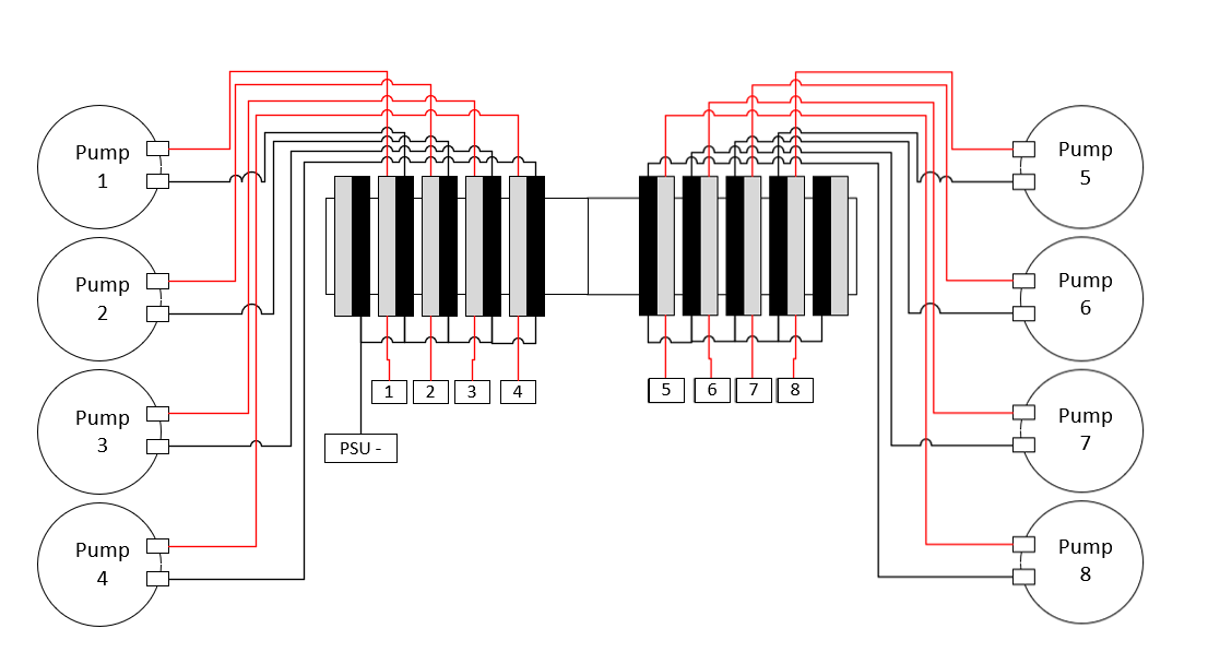
The first part I decided to tackle was the pump design. Not only is this the easiest part, it is also a part of the project that is the least likely to change if I modify the overall design of the project. It’s plain and simple, the pumps need power. I put everything on a DIN rail and wired everything up per the diagram below.
Logic Design
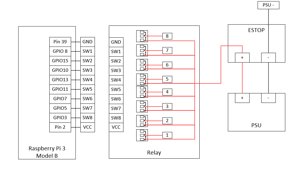
I really enjoy using Raspberry Pis for relay control. It’s definitely overkill but I’ve collected many of them over the years and they just work. I’m using a Raspberry Pi 3 Model B so the corresponding pin out referenced in my diagrams is here. If you use a different Raspberry Pi or some other device, your pin out will vary.
I connected the Raspberry Pi’s GPIO pins, VCC, and GND to the Relay. Then, I connected the PSU to the ESTOP and the ESTOP to the Relay. This way if for whatever liquid starts spraying everywhere, we have a quick way to kill the power. It’s important that the Raspberry Pi and the PSU be physically isolated as the voltages are quite different between the two hence the use of the relay.
Note, all the connections to the relay are NO (Normally Open) so that no current flows to the pumps in the default state. The connections via the ESTOP are NC (Normally Closed) so that only when the button is pressed the current flow stops.
Programming
For the programming, Python made the most sense. It’s what I’m familiar with and has great libraries for the Raspberry Pi.
The code to turn on each pump for 60 seconds is below:
import RPi.GPIO as GPIO
import time
import os

GPIO.setmode(GPIO.BOARD)

def cycle(x):
    GPIO.setup(x, GPIO.OUT)
    GPIO.output(x,GPIO.LOW)
    time.sleep(60)
    GPIO.output(x,GPIO.HIGH)

pump5=3
pump6=5
pump7=7
pump8=11
pump4=13
pump3=10
pump2=15
pump1=8

pumps = [pump1,pump2,pump3,pump4,pump5,pump6,pump7,pump8]

cycle(pumps)
With just 19 lines of code, you have the building blocks to build functions to mix drinks between all 8 of the pumps. The time each pump is on will directly correlate with how much liquid is dispensed. In order to determine the quantity of liquid dispensed, I turned a pump on for 60 seconds and weighed the liquid dispensed. Do this a few times to ensure an accurate number.
mL of liquid / 60 seconds = flow rate (mL / second)
Knowing this value will ensure you never overflow the cups you dispense into.
Programming Continued
One of the fail-safes in the code that needed to be added was to ensure the state of the GPIO prior to making any modifications. Therefore, I built a small reset function and called it on the pump array (just like in the cycle function above).
def reset(x):
    GPIO.setup(x, GPIO.OUT)
    time.sleep(0.2)
    GPIO.output(x,GPIO.HIGH)
Note that in all the above samples, GPIO.LOW = ON and GPIO.HIGH = OFF
Physical Design
The wood to build the stand for the robot drink machine consists of a piece of 3’x6’x1” and 3’x4’x1” plywood board. Wood screws, wood glue, and angle brackets were used to place the smaller board in the center of the longer board, lengthwise, to make an upside-down “T” shape. Sanding the boards and throwing a coat of paint on them is recommended. Screw the angle brackets behind the upside-down “T” to add some rigidity to the upright board. Screw the 3/4” 90 degree PVC fitting at the center of the upright board with one face of the fitting facing downwards so that the tubing can be routed through it and into the drink containers below.
Credits
-
Austin Scott for his original Sir-Mix-a-Bot
-
My friends for sharing in the joy of making and for naming my build of this robot “Wells”