PLC Training Board
June 2021
Goal
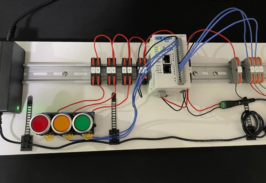
The goal for this project was to develop a portable and comprehensive Programmable Logic Controller (PLC) training kit. The target demographic for this training kit was individuals with little experience in Electrical Engineering / Control Systems / PLCs.
Inspiration
The inspiration for this project came from the SANS Institute’s course ICS515: ICS Visibility, Detection, and Response which has a physical training kit containing a PLC. I wanted to make one myself for the joy of building it but also so that I could teach others with it.
What can I teach with this Training Board?
- Basic Electrical Circuits
- Engineering Design Process
- Programmable Logic Controller Basics
- Fundamentals of Control Systems
Materials
| Component | Quantity | Product Page | Price |
|---|---|---|---|
| CLICK PLC C0-10DRE-D | 1 | Link | $169.00 |
| 12.9” x 35mm x 7.5mm Aluminum DIN Rail | 1 | Link | $6.99 |
| DIN Rail Terminal Blocks | 1 | Link | $25.98 |
| 18 Guage Solid Core Wire | 1 | N/A | < $10 |
| Red Yellow Green Momentary Push Button | 1 | Link | $14.99 |
| 24V 3A DC Power Supply Adapter | 1 | Link | $14.99 |
| Led Signal Tower Stack Lights | 1 | Link | $18.90 |
| Cable Management Clips | 1 | Link | $9.99 |
Total Approximate Cost: $270.84 + Wood (~$15) = $285.84 USD
Design
For the initial design work, I split the project into three pieces, the wiring design, programming design, and physical design.
Wiring Design
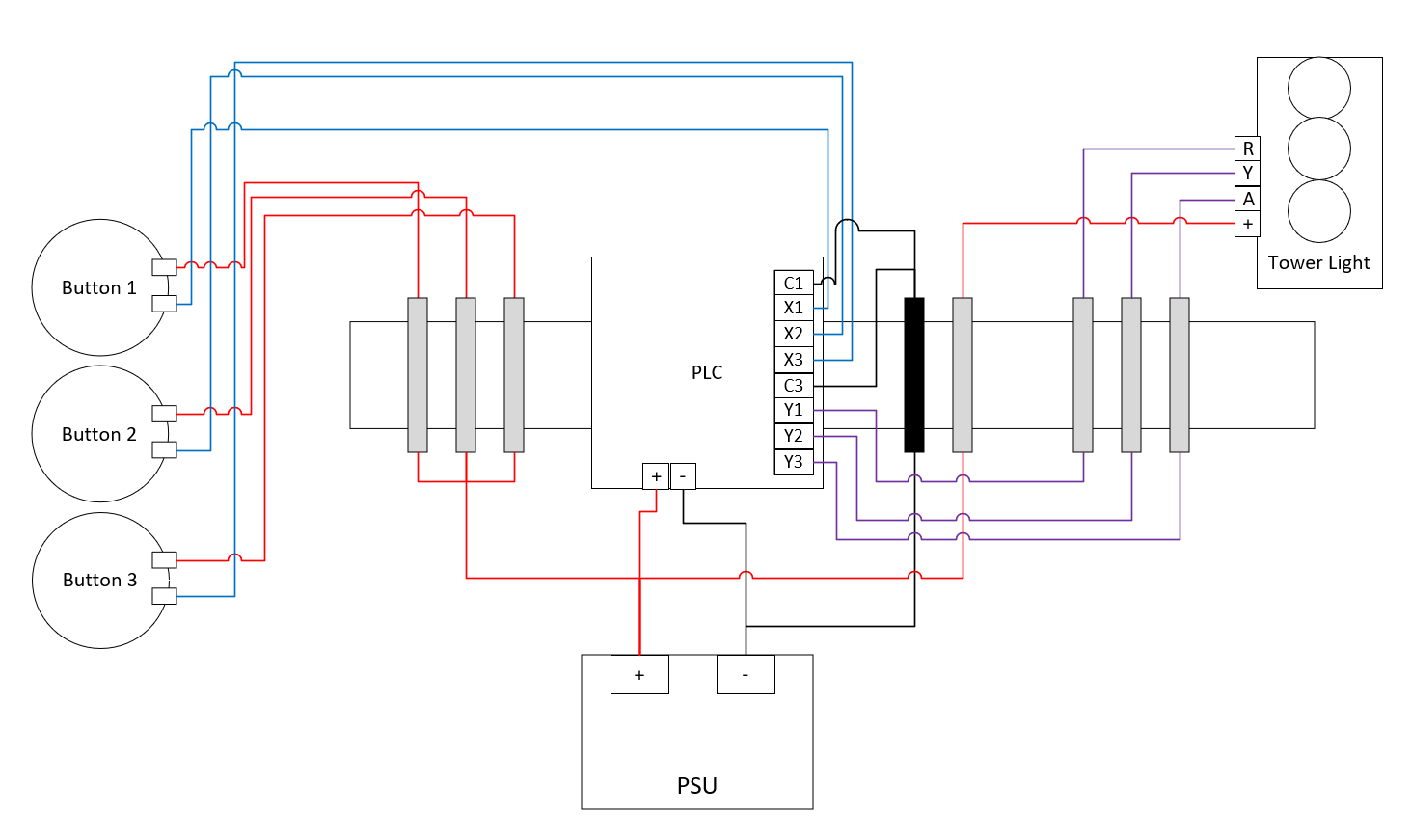
For the wiring design nothing too fancy is going on.
- Power is supplied to the PLC and the Stack Light via the PSU
- Push Button inputs map to X1, X2, and X3 on the PLC (Sinking Type Input, learn more about this here)
- PLC Outputs map to Y1, Y2, Y3
- PLC Common ports are all connected to ground
Programming Design
In order to tell the PLC what we want it to do given the various inputs (X1/X2/X3) and outputs (Y1, Y2, Y3), we need to program it. To do so, I used the CLICK Programming Software.
To learn how to use the CLICK Programming Software, check out their training page. Since this project in particular resembles the first section of that page, I will omit the ladder logic file.
However, for those curious, the general layout is as such:
- X001, X002, X003 are all “Normally Open” Contacts which connect to their respective Output Coils (Y001, Y002, Y003)
- Note that the inputs and outputs have a “00” prefix when referencing their Bit Memory Addresses
- An “END” instruction is required on the last rung of the ladder
Physical Design
The board used to attach the DIN rails, PLC, buttons, and stack light (not pictured) is a 6’x2’x1” piece of plywood. Wood screws are used for the DIN rail mounting. Cable management clips and a bit of hot glue for the power supply was used to keep everything together. The plywood was sanded and given a coat of paint.

